Heading:
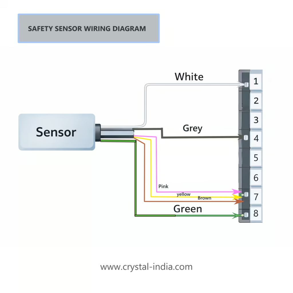
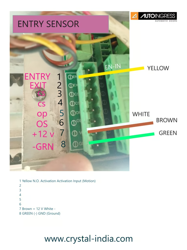
Safety Warning: Normally 6 wires need to connect to control panel. Actully there are 8 wires come from the safety sensor. but we normally connect 6 wires to the control panel. it is like this.
Power Supply. Motion Detection Action, Presence Detection Action.
Diagram Image:
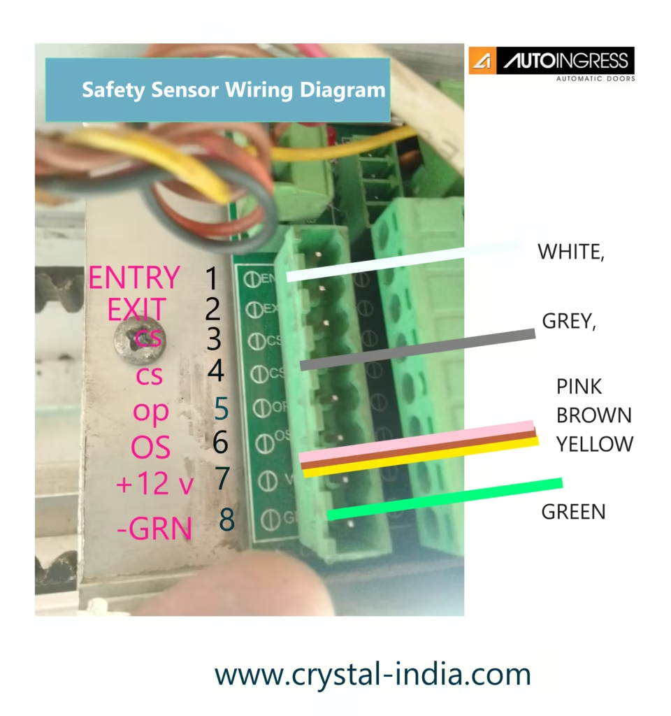
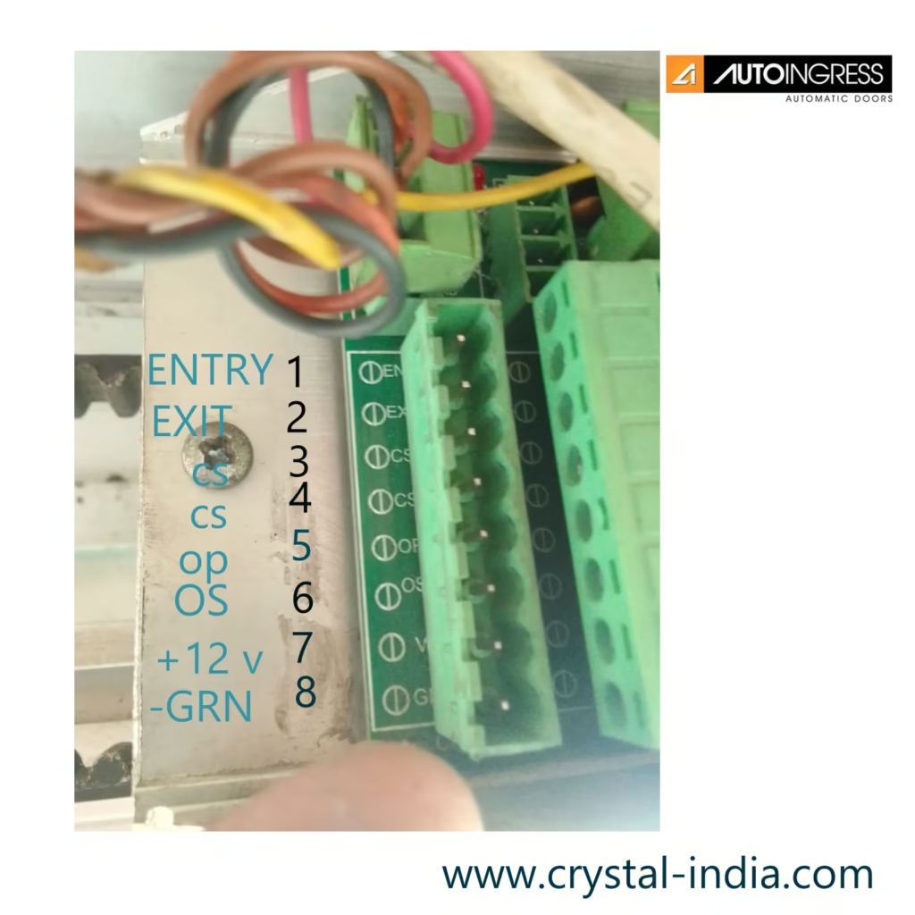
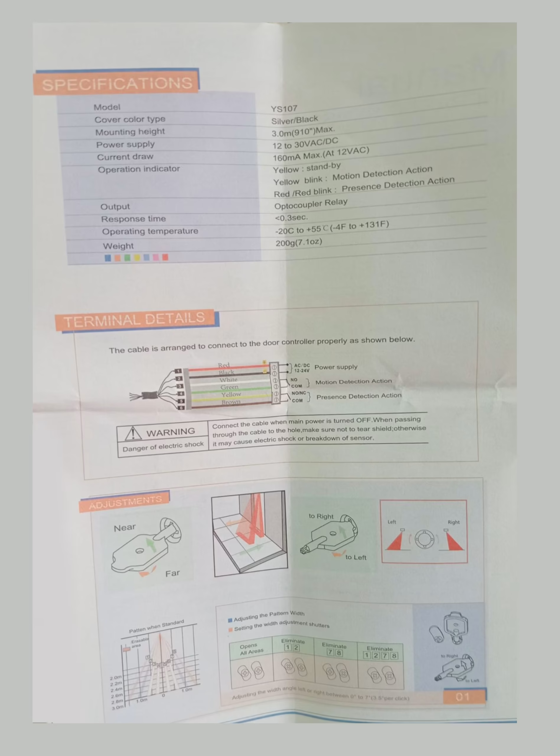
Terminal Descriptions:
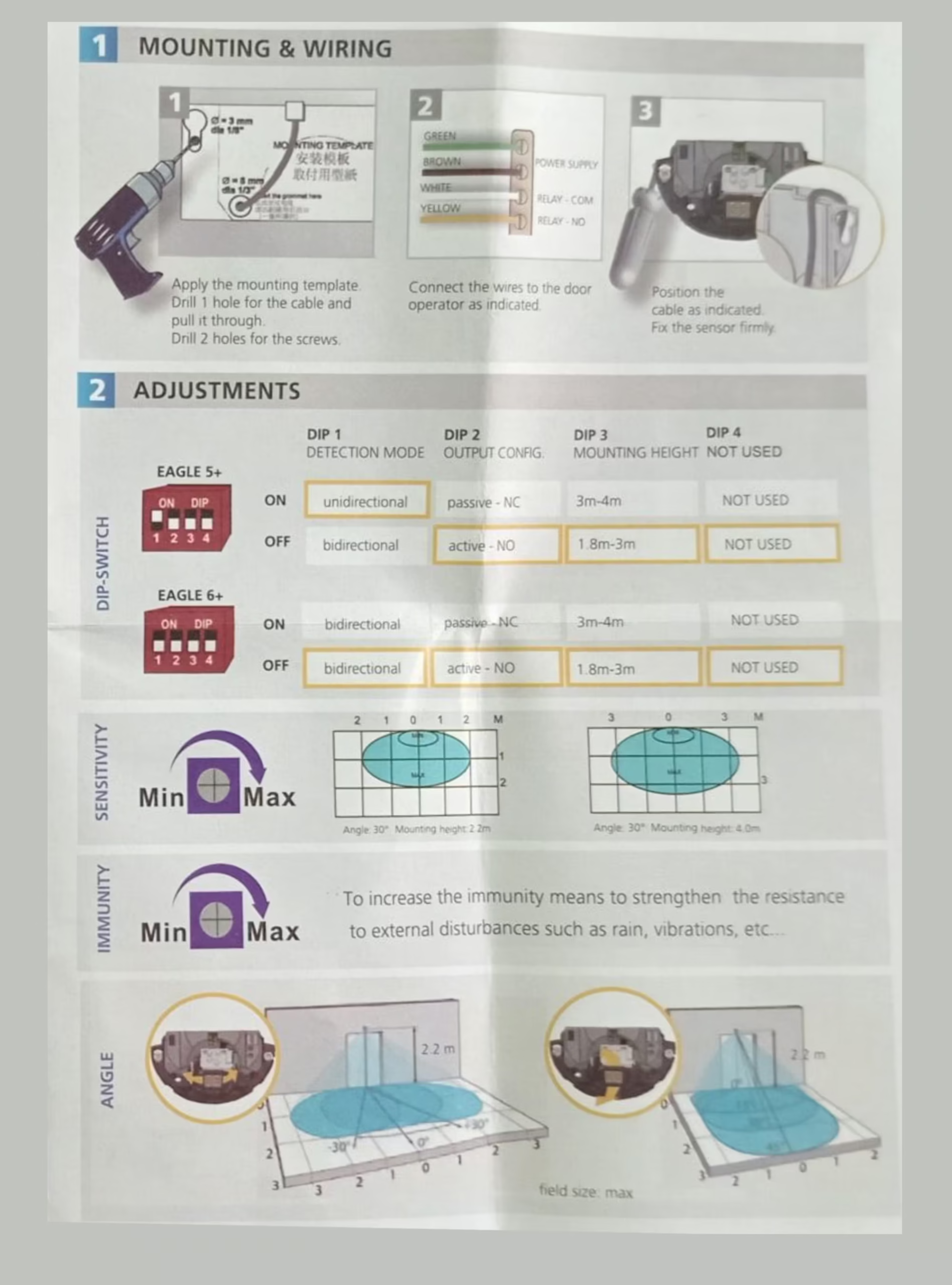
Dip Switch Settings:
Type AS5 V7-5: Commissioning Instruction: Models LS300 + LP & LS220B + LP + ELP + LSW – LP
- Ensure the automatic door operator is fixed securely, the door are hung plumb and slide freely to full open and close positions.
- Check the floor guide and anti-rise wheels are not too tight and allows enough travel. Adjust the height if needed to provide
- adequate floor clearance (approx 10mm). Set the mechanical stops securely. If fitted check the manual lock engages correctly.
- Wire up all switches and sensors as per the diagram below. Set the mode to auto and turn the mains power on.
- The door should slowly open first. If it closes instead then switch the power off swap the motor direction by swapping the
- supply wire to the motor. Turn the power back on to reprogram then operate the doors several times and plug the batteries.
- If the settings need changing, press the setup key on the mode pad and key in the 4 digit master code then press the enter key.
- Using the up or down arrow keys choose the setup parameter or setup function by pressing the enter key. Press the arrow keys
up or down for the sub parameter or the function required. Press enter to select or exit to escape. Once selected change if
required using the up or down arrow keys. Press enter to retain the change or exit to discard. press the up or down arrow key
to select the next function or parameter to change. Press enter to select or keep pressing the exit key to return to the previous
menus and/or to return from the programming screen to the normal rolling display.

- To change the operational mode press the mode key and key in the user code followed by the enter key. Press mode key to
change from the current mode to the desired new mode.
8 Pressing the setup key and using the user code will allow the alarm reset for 48 hours, user code change and managed lock. In
lock mode only, managed lock enables locking of the doors by overriding the safety sensors until the next mode change.
9, The master code is used for permanent alarm reset, parameter and function changes, new user code change and time clock settings..
- Pressing the exit key and confiriming by the enter key will open the door in all modes for engress except when disabled; then
pressing the enter key followed by the user code will open the door in all modes.
PY
Please note that all parameter and functional changes should only be carried out by competent personal to avoid injuries or accidents. The commissioning is to be carried out to AS5007 and BCA requirements with particular notice for the safety and engress requirements.
The following items are available on the mode pad:
Modes: Open, Auto, Exit, Lock and Manual, Plus additional Climate Open, Climate Auto, Climate Exit, Climate Lock and Safe Mode
User setup: 48 hour reset, user pass-code change, Managed lock, Time and Day setup, People Counter, Register door, View settings and Diagnose faults.
Setup Parameters; Open, Close, Slow open and slow close speeds, Open and close current limit, Dwell Time Auto, Dwell Time Lock Open and close Trim, Slow
Boost, Climate, Open brake time, Reverse delay, Soft Start trim, Open Safe trim, Hold Open On open Safe.
Safety Functions: Battery, Failsafe, Service, Push & Go, Open/Close Safety Sensor Relay o/p, Open/close Safety Sensor Monitor, Buzzer Enable/Disable, Key
pad entry enable/disable, Climate options, Lock type, Back check and Latch Resistance, Keypad Mode Code disable.
Factory Setup: Master-code Change, Factory registration, Service phone, Door type, Default Settings, Select Battery, Select key Pad, Reset Service Timer,
Buzzer Setup.
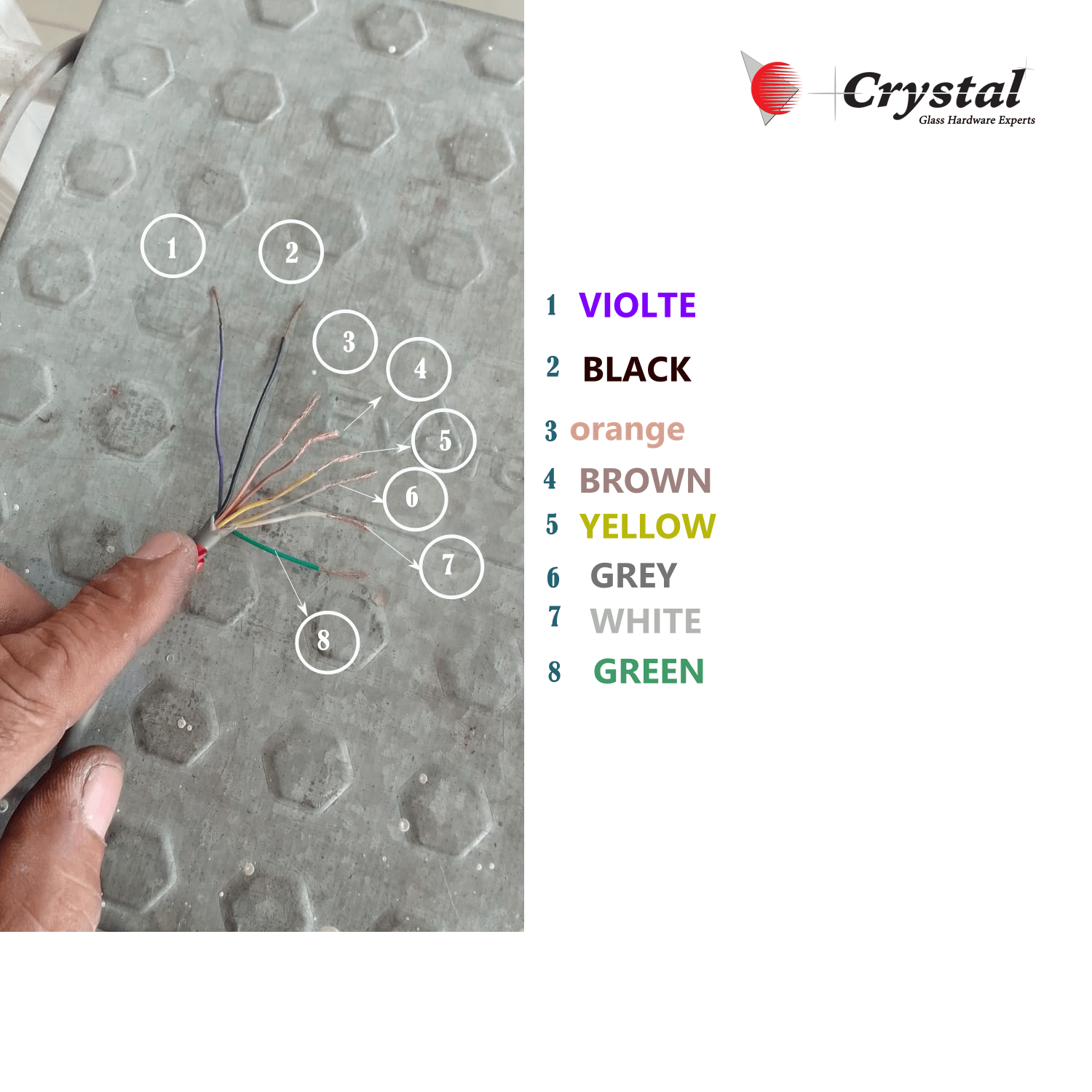

Entry Sensor Wiring Diagram

BEA Sensor Old Model With 6 Wire Connections for Zensafe Model

BEA ZENSAFE SENSOR CONNECTION DETAILS OLD


